#00356 Russia KV-1 (Model 1941) "KV Small Turret" Tank
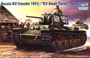
Out of the box, this kit represents a KV-1 Model 1940 with an early welded turret and F-32 gun, manufactured in May or early June 1941, just prior to the introduction of the ehkrany program. Optional parts are also provided to build a KV-1 Model 1939 built between October and December 1940 with the earlier L-11 gun, though you will need to make some modifications to the kit parts for complete accuracy.
Like all the Trumpeter kits, the lower hull is comprised of a tub that includes the underside, hull sides and the lower front hull. The underside includes bolt detail for the torsion bar attachments and engine bearers, the filled bolt holes along each side of the underside plates, the drain ports for the transmission and final drives, and the emergency escape hatch. The oil drain port under the forward left-hand corner of the engine compartment is missing however, and the circular access port beneath the engine is represented as a recessed circle where it should be flush. If you wish, you can fix this with a disc of thin stryene sheet.
The actual hull side plates are separate components that are added to the lower hull tub. Note that there are certain holes that must be opened in the hull sides and others that are optional depending upon whether you decide to fit the applique armor to the upper hull sides. You must do this before attaching them to the lower hull tub. These holes are illustrated in Step 1 of the kit instructions.
The hull sides include integrally molded base plates for the suspension swing arms, shock absorbers, mud scrapers and idler mounts. The bolts on the shock absorber mounts have the correct conical heads, and the swing arm mounts include the grease fittings. The plates include six bolt holes beneath each return roller mount, as on the real vehicle. The middle row of holes are used as the locating holes for the separate return roller mounts and are slightly larger than the others but you can, if you wish, depict a damaged vehicle with a missing return roller mount.
The lower rear hull is a separate component that fits between the hull side plates. The fit of this part is not very precise and some trial fitting will be necessary to ensure that it lines up correctly with the hull sides. The part should in fact overlap the bottom of the hull tub slightly. The lower rear hull includes an integrally molded tail light housing, with a separate clear part for the tail light itself. The grille beneath the rear hull overhang and the exhaust air deflector plate are both included and the deflector plate is commendably thin. However, you may still wish to replace it with a brass part if you want to depict some operational damage in this area, which is evident in many photographs of KVs in service.
The lower rear hull includes integrally molded base plates for the rear towing eyes, and these include filled bolt holes. The forward towing eyes are separate component that attach to hull tub, and also include the filled bolt holes. The raised circular marks for the bolt holes are, in my opinion, a little too prominent but can be reduced with some light sanding. All the towing eyes feature separate towing shackles with integrally molded retaining pins.
As implied above, the suspension swing arms are separate components with hexagonal locating plugs that fit into holes in the hull sides and ensure the correct angle. The swing arms are of the correct early pattern and include the correct six retaining bolts on the torsion bar caps. The shock absorbers are also separate pieces that fit onto the base plates molded onto the hull sides. The separate components provide good detail definition but you must take care to make a good joint since the main shock absorber housings and the base plates were in fact single castings.
The sprocket mounts and return roller mounts are separate components that accurately depict the shape of the real assemblies. Like the return roller mounts, the hull sides beneath the sprocket mounts include bolt holes as on the real vehicle.
The idler mounts and adjustment mechanisms are separate assemblies with three parts each. Again, the parts provide good detail but you should take care to fill and sand the seams on the 'big ends' of parts A3 and A7.
The nose plate includes 11 filled bolt holes across each face. These are correct for a May/June 1941 vehicle but as noted above, are possibly a little too prominent and would benefit from light sanding.
The kit includes pressed steel two-part resilient road wheels with lightening holes and six cooling vents on the inner discs, as fitted from October 1940 until the end of June 1941, and which are therefore correct for a May/June 1941 production example. The return rollers are the pressed steel pattern with rubber rims, and are also correct for this variant. The sprockets feature the correct 16 bolts securing the convex hub cover, and the idlers include the grease fitting on their hubs. The mud scrapers are the correct welded design, though you must take care when attaching them to ensure that the joints between the separate mud scrapers and the base plates molded onto the hull sides are filled, since the base plates on the rear vehicle were part of the mud scrapers themselves.
As on all Trumpeter's KV kits, the tracks are the reinforced Omsh pattern that were in fact not introduced until July 1941, and are therefore incorrect for a vehicle completed in May or June. However, the differences are very minor and will go unnoticed by most observers.
The forward portion of the upper hull, including the glacis plate, driver's front plate and forward hull top, is molded as a single piece. The glacis plate includes integrally molded bases for the front fender brackets, and these include bolt detail. The protective cover for the antenna mount and the armor fillet protecting the underside of the machine gun mount are separate moldings. The armor fillet lacks the drain hole in the forward face, but this can be easily added with a hobby knife or the edge of a file.
The kit provides optional applique armor for the lower front hull and the driver's front plate. The applique armor plates first appeared in May and became more common over the next few months. By mid-July, they were almost universally fitted to new vehicles. Note that both armor plates must be fitted, or neither. The plates were fitted together or not at all. If you decide to use the applique armor plate, you must open up the appropriate holes on the inside of the forward upper hull part (A27). Again, this is noted in Step 1 of the kit instructions.
On the driver's front plate, the kit provides a well-detailed and accurate machine gun mount, driver's visor, headlamp and siren. The headlamp and siren include integrally molded brackets but these are best replaced with aftermarket parts, scrap styrene or brass. Depending on whether you fit the applique armor or not, there are alternative parts for the power conduit. Use part N8 for a vehicle without applique armor, and part D16 for a vehicle with applique armor.
The crew hatch in the forward hull is the correct early pattern with rounded edges, and the grooved hatch coaming, also appropriate for a May/June 1941 vehicel, is a separate part. The kit includes the hinge, locking bars and operating cam on the interior face of the hatch cover, but the grab handle and operating handle are missing. The driver's epsicope cover includes a flange, which is appropriate for a May/June 1941 example. The fuel, oil and water filler caps are all present, correctly positioned and of the correct design.
The bolt configuration on the engine compartment and transmission compartment roof plates is correct, with eleven equally spaced bolts across the rear edge of the engine compartment roof plate, and the same number on the front and rear edges of the transmission compartment roof plate. The bolts have the correct conical heads for a May/June 1941 vehicle. The lifting eyes are present and of the correct shape, including those beneath the turret bustle. However, Trumpter includes four lifting eyes on the transmission compartment roof plate, rather than the correct two. Omit the two lifting eyes in the rear corners of the plate, and fill their locating holes.
The engine access hatch is the correct early pattern without the inspection port, and with only a single lifting eye. The kit actually includes the inspection port and gives you the option to drill out the hatch and add the port. Do not do this; it is incorrect for a May/June 1941 vehicle. The cable and hook used to secure the hatch in the open position are provided as a separate part.
The radiator intake screens are separate moldings. The kit includes both early and late pattern screens, but the late pattern are appropriate for a May/June 1941 vehicle. The screens are molded solid however, and the model would benefit from their replacement with etched brass items. The exhausts include open ends, avoiding the need to open them up with a drill or knife.
The transmission maintenance hatches are also separately molded and the kit includes hinges allowing you to position them in an open position.
The kit includes the regular curved rear hull overhang which is appropriate for a May/June 1941 hull.
As noted in General Comments, the fenders are Trumpeter’s wider version, which is appropriate for many vehicles and can be altered if you wish using the steps described here. The kit fenders feature integrally molded flanges for the fender brackets with the correct six attachment bolts. The hull sides include integrally molded flanges with the correct three bolts. Only skeletal brackets are provided, as is correct for this variant.
Optional parts are included for applique armor on the upper hull sides. This was not uncommon on May/June 1941 examples, so check your reference for the vehicle you are modeling. If you wish to use the applique armor, you must open up holes on the hull sides before you attach them to the lower hull tub.
The kit includes three revised large rectangular stowage boxes for
the fenders, and the instructions show the correct positioning on the
number 7, 8 and 10 positions. A cross-cut saw and its mounting
bracket are included for for the number 5 position on the left-hand
fender, but the saw and its bracket were relocated inside the stowage
box on the number 10 position in March 1941. You should therefore
omit the saw and not open up the locating holes for it on the
fender. The cylindrical stowage tube for the barrel cleaning rods
is provided for the number 6 position on the right-hand fender, and
this is appropriate for a May/June vehicle, though the tube was
eliminated in late June/early July.
The kit provides both early and late pattern radiator intake
screens. Most Model 1940s with the regular curved rear overhang
also carried late pattern screens, but the early screens provide the
option to model an early production example or a Model 1939. As
noted above, the mesh is molded solid and would benefit from
replacement with aftermarket items. Eduard provide both early and
late pattern screens in their “Zoom” series.
The kit includes the correct early towing table ends with grommets and
“sleeves”. However, you will need to drill out the ends to
accommodate the brass wire cable provided. The rear attachment
brackets and turnbuckles to attach the cables to the hull sides are
also included. Each bracket and turnbuckle is molded as a single
assembly however, and you may wish to cut away the brackets and
substitute aftermarket parts for better detail definition.
The kit provides an early welded turret with butt-welded corners, which
is appropriate for a May/June 1941 example. The front and rear
faces include the filled alignment pin holes. However, the turret
roof features ring-shaped marks that were characterisic of turrets
manufactured in Chelyabinsk from June 1941 onward so if you wish to
depict a vehicle manufactured by LKZ, which was the predominant
manufacturer in the early summer of 1941, you should sand away the
marks on the roof, leaving those on the front and rear faces.
The episcope and ventilator covers include flanges, which is correct for this variant. The conical covers for the periscopic sights feature bolt detail on their rear sides but lack the small holes in the tops. These can be easily added with a fine drill bit. The grab handles for the edges of the turret roof are included and correctly located, though you may wish to replace them with brass wire.
The turret hatch includes the base plate for the P40 anti-aircraft machine gun mount, but this is incomplete and lacks the rectangular socket into which the butt of the machine gun was placed when travelling. For accuracy, you should add this from scrap or aftermarket parts. The hatch cover itself includes a socket in its center but this is incorrect; the socket was not present on KV-1 turret hatches (though it was present on KV-2 turret hatches). Fill the socket and sand it smooth, leaving the hinge bolt detail. The hatch cover provides some interior detail including the locking bars and cam, but the locking bars should be slightly offset to accomodate the machine gun mount. The operating handle and grab handle are also missing. If you wish to display the hatch in the open position, you should replace the operating mechanism with aftermarket parts.
The F-32 gun and its mount are accurately depicted and the gun barrel is a single piece with a hollow muzzle. The kit part is adequate but you may still wish to use an aftermarket barrel instead. The rain guard above the mantlet is commendably thin and includes bolt detail. The configuration of the rain guard is correct for an F-32-armed KV-1, with the rear edge turned up and riveted to the front face of the turret. The turned-up edge is molded integrally with the turret shell, so you should take care to ensure a seamless join between the parts.
As noted above, the kit includes parts for the L-11 gun and mantlet,
allowing you to depict a KV-1 Model 1939 as built between October and
December 1940. However, the kit part depicts the early L-11
mantlet with three attachment bolts on its right-hand side and a bolt
on the upper face. The mantlet was revised in August/September
1940, eliminating the central bolt on the right-hand side, along with
the groove in the side of the recuperator cover and the bolt on the
upper face of the recuperator cover. It is a simple matter to
make these changes and correct the kit part.
In order to create an accurate Model 1939 however, you must also modify
the turret to depict the early construction method by sanding away the
torch cut marks from the front and rear corners of the turret
sides. The ventilator cover on the turret roof, and the episcope
covers on both the turret and hull lacked flanges on the Model 1939, so
the molded-on flanges must be removed. The shielded machine gun
mount on the turret rear face must be removed and replaced with the
earlier ball mount, which is not included in the kit. You must
also modify the fender stowage boxes to represent the earlier pattern
without reinforced lids or handles, and mount the cross-cut saw on the
number 5 fender position.
The kit provides an optional pistol port to replace the machine gun mount on the driver's front plate, with the intent of allowing you to depict a KV s malenkiy bashniy built between July and October 1940. To accurately represent this variant, you must make the same changes as described above for the KV-1 Model 1939.
